A High Level Introduction to T-Splines in Dynamo by Zach Kron

What is a T-Spline?
A T-spline is a special kind of geometry that allows users to sew together lots of smaller surfaces into continuous, smooth elements using minimal sets of control points or cages. More specifically, a T-spline is a surface type that is typically useful for modeling organic or topologically complex forms. T-splines are compatible with both NURBS surfaces (a geometry with its roots in aerospace and automotive modeling) and Subdivision surfaces (with its origins in animation). In terms of modeling, workflows are very similar to low-polygon mesh modeling, but which produces smooth and continuous NURBS surfaces.
For a deeper look at the technology itself, please visit this page
http://www.tsplines.com/about/technology.html
For an excellent history of the the basic idea of the Spline and its impact on computational geometry, including the specific lineage of T-Splines, check out this article.
http://www.alatown.com/spline-history-architecture/
Why “Experimental” in Dynamo?
T-Splines modelling technology is now experimentally exposed in Dynamo to get initial feedback on the tools while we figure out exactly how we are going to expose them in the future. The Dynamo Team is working in collaboration with folks in the Autodesk Automotive group exploring what the possibilities and potentials are for procedural design workflows in Automotive and other industries adjacent to AEC.
We considered keeping the tools hidden while we got it perfect, but we thought it was more valuable to have them at least partially exposed. In the future, we will be reorganizing their arrangement in the browser, probably doing some renaming, and adding/removing nodes from the library, so don’t get too hung up or comfortable with the particulars. Since this is an advanced functionality that may be useful only in certain non-standard workflows, these nodes by default will be hidden in the library and will not interfere in node search results unless explicitly turned on.
We originally wanted to expose the tools like a package, as we have with the Mesh Toolkit. However, T-splines is already part of the underlying Geometry engine that Dynamo Studio and Dynamo For Revit use (the Autodesk Shape Manager), and there are some technical obstacles to having packages simply turn on and off this functionality.
How can I use them?
To expose the tools, go to Settings > Experimental menu and check “T-Splines”, then restart your Dynamo instance. You will now find the nodes available in the Geometry menu. Currently there are about 150 new nodes that are a subset of the existing geometry library. The new functionality offers a wide range of capabilities to create and edit T-Spline surfaces and also conversion to and from NURBS and meshes.
To get started, you need to actually create a t-spline surface. These tools are in Geometry > TSplines > TsplineSurface. Here you will find a huge number of tools for creating primitives (Sphere, Cube, Cylinder, etc) similar to how you create them in “regular” geometry, but that are all of the special sub-class of TSplines. You can also convert regular surface elements into T-Splines, and create them from typical curve and point based methods, like extruding a curve or revolving a profile around an axis.
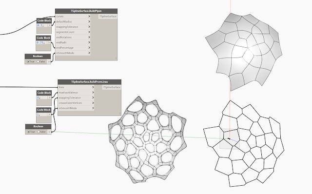
Along with these more traditional methods which have recognizable counterparts in regular modeling techniques, you can also create T-splines by providing a “cage” of lines which can be interpolated into a closed or open surface, or a skeleton upon which can be hung a closed T-spline body. These tools allow you to create forms that would be incredibly difficult with relatively low initial definition of design constraints. Check out TSplineSurface.BuildPipes and TSplineSurface.BuildFromLines.
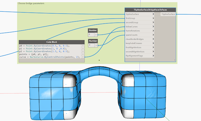
Manipulations of the resulting T-Spline elements is where the fun really starts with Bridging tools, Creasing, Thickening, and other tools to customize your output
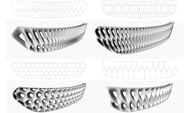
Here are a number of examples and sample files of the tools in action.
For more ideas about what you can do with this technology, please visit this page
http://www.tsplines.com/applications.html
Some additional ground rules for getting started
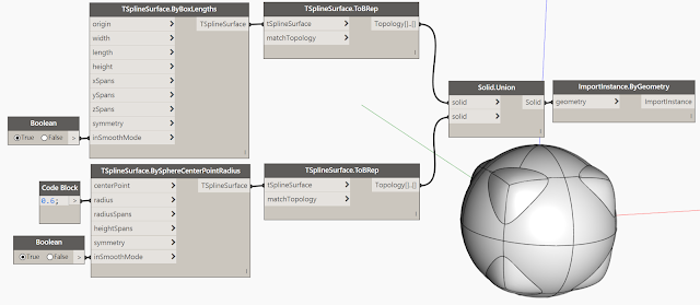
T-splines occupies an interesting region between Polygonal modeling and Surface modeling by using many of the construction techniques of Mesh modeling with the accuracy of Nurbs Surfaces. There are whole dissertations to write on this, but assume that T-splines are not regular Surface geometry or Meshes, and in this way they also need their own conversion methods to interact with these other kinds of forms. To allow for the interaction of Meshes and Surfaces/Solids, there are 2 nodes in particular to be aware of in the experimental tools: TSplineSurface.ToBRep and TSplineSurface.ToMesh which output converted elements in each of these geometry classes.
Finally, it’s important to understand the difference between Geometry and Topology. Getting your head around Topology is needed for most advanced form making, but is particularly necessary for T-splines. Topology is the way we define the relationship between Geometry elements, and can be seen in the difference between often conflated terms: point/vertex, curve/edge, and surface/face. Points, Curves, and Surfaces are separate Geometric elements that exist in isoation. Vertices, Edges, and Faces are defined by the Geometry relationships they represent, and they have information about things like neighboring elements. A Curve only knows things like it’s own start and end points, but an Edge can be queried for it’s adjoining faces, a vertex for it’s edges, etc. T-Splines have a huge number of capabilities to manipulate forms based on things like understanding what edge are internal to a form, which are on the border, or how many neighbors it has.
Some known issues
- Once you get into larger constructions, smoothed T-spline elements can get really SLOW! This is largely do to an over smoothing of the surfaces, which we will adjust. In the meantime, while you are playing around with settings and interacting with your operations, you can keep the Smooth setting on creation nodes set to “false”, which is their default value.
- For the moment, this functionality will not be available when Sent to Web from Dynamo Studio.
- Preview geomtry does not alway appear after indicator says “run complete” and resulting geometry creation node sometimes needs to be selected
Thanks for trying out the tools, please chime in on the Forum with any comments or questions, we have also started a conversation with this forum post, but please feel free to add more.
-The Dynamo Team
Special shout out to Tom Finnigan, Matt Sederberg, Aparajit Pratap, and the badasses over at Modelab for the great work they have all done making T-Splines in Dynamo happen.


Comments: 2